29 Results
View results:
Sort by:
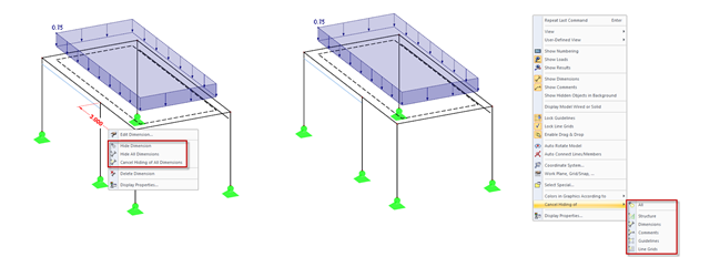
In addition to the options of Project Navigator - Display, you can modify the visibility of structures (members, surfaces, and so on) and guide objects (dimensions, comments, guidelines, and so on) in the menu and toolbar using the shortcut menus.
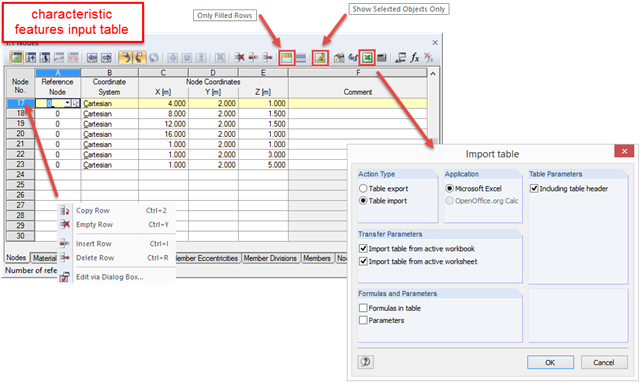
RFEM and RSTAB are programs where graphical input prevails. All data can be entered using dialog boxes, and the structure of the Project Navigator is optimized for input using the mouse. Nevertheless, you can always speed up the tabular input to reach your goal immediately.

RFEM and RSTAB offer many display options in the Display Navigator. They can be completely different, depending on their function. You often have to click several times to make certain changes. If you want to optimize your work, you can create user‑defined views. In these views, you can save all specified settings. The following example illustrates this principle.
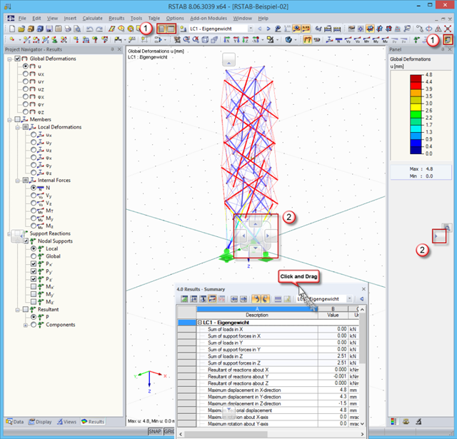
In order to use the working window area optimally for the graphical input of model data or for result evaluation, there are various options for arranging Project Navigator, the table, and the result panel.
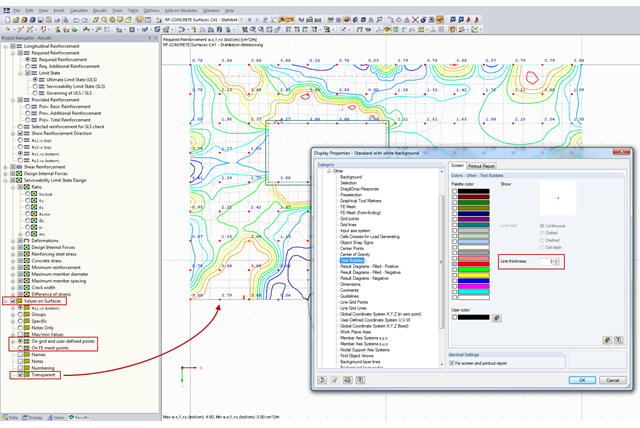
You can document the results of RF‑CONCRETE Surfaces graphically in the printout report. To do this, the "Values on Surfaces" setting is often selected in the Results Navigator of RF‑CONCRETE Surfaces. A text bubble including a result value is displayed, and depending on the settings in the Results Navigator, it can be displayed on the surface grid points, manually defined points, or in FE mesh points.
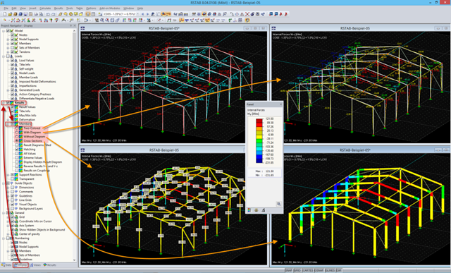
In the RFEM and RSTAB work window, four display modes are available for the results of members. They can be selected in the Display Navigator under "Results" → "Members".
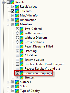
In order to display the internal forces of rigid members, it is necessary to select the corresponding option under ‘Results’ → ‘Members’ → ‘Results on Couplings’ in the Display navigator.
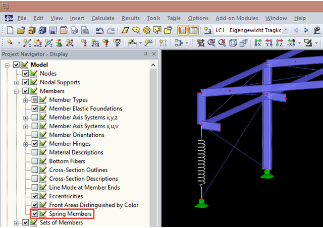
You can display spring members in the Display Navigator. A spring member is displayed as a helix by default. Clear the "Spring Members" check box to display them as normal lines.
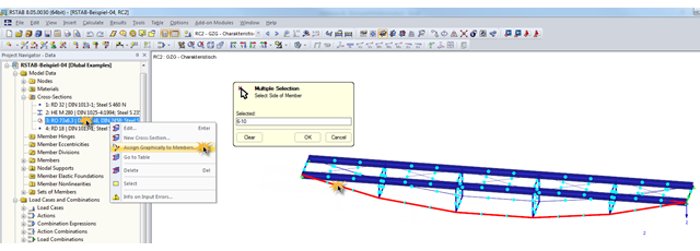
During the optimization of a structure, the individual cross‑sections may have to be modified several times. This can be done very quickly using the function "Assign Graphically to Members", which is available under "Cross‑Sections" in Project Navigator – Data.
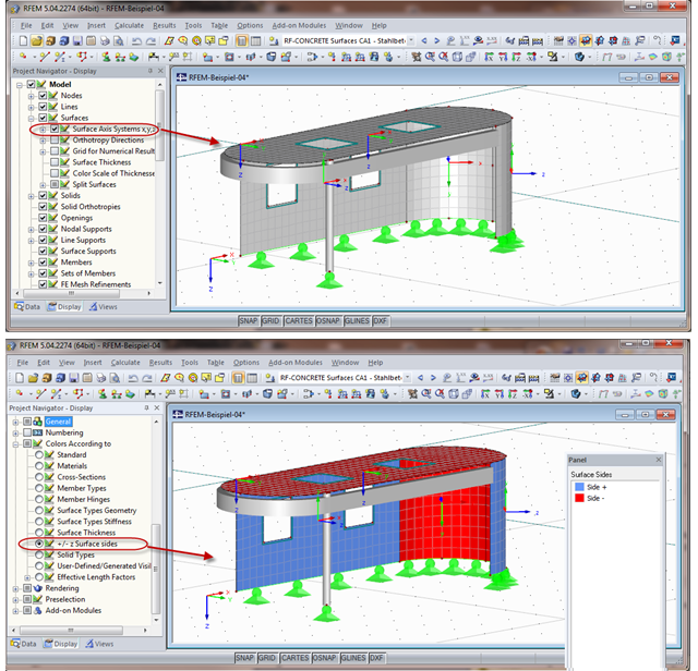
When calculating the surface reinforcement in RF-CONCRETE Surfaces, the result values for both surface sides +/- z are available. If you are unsure which side of a surface is the positive or the negative z side, you can hide the local coordinate system of each surface in the RFEM Project Navigator - Display under "Model" → "Surfaces" → "Surface Axis Systems x,y,z". In the case of complex structures, this can quickly become confusing. Displaying multiple axis systems makes it difficult to recognize the incorrect direction of a surface, for example (see the figure on the top).